Usage
In the following sections, we present a simple overview of the basic features of P4-Utils. In case you are looking for more advanced options, please have a look at the advanced usage section.
To make the explaination simpler and more concrete, we consider the following network example. We will go through the configuration files that allow the user to define and use such a topology.
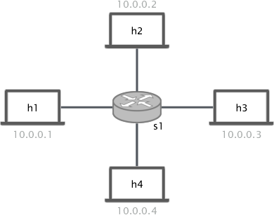
As we can see in the figure above, we have four hosts connected to a switch. All the
switches are placed in the same subnetwork 10.0.0.0/16. We have to create the
network and establish connectivity among the hosts via L2 forwarding.
Important
For more examples and use cases, we recommend to check out the repository P4-Learning. It is a collections of working examples and exercises that are very helpful to start programming with P4.
Network Setup
To create a network we can use two different methods:
- the Python method relies on writing a network defining script
that makes use of
NetworkAPI, - the JSON method, on the other hand, relies on writing a JSON network
definition file using the specifications of the parser
AppRunner.
Python
The Python method is a newly introduced feature that allows to programmatically
specify which elements are present in the network and how they are connected.
It is based on the NetworkAPI, an API that
has a lot of methods to precisely define the network structure.
Let us create a file called network.py. In order to define the network, we first
need to import the required module and create a NetworkAPI object:
from p4utils.mininetlib.network_API import NetworkAPI

net = NetworkAPI()
We can also set the level of details for the log shown during the execution of the script:
net.setLogLevel('info')
Other important options are those involving ARP tables of hosts. One can choose
to disable static ARP entries for hosts within the same subnetwork and their
gateways by using the methods
disableArpTables() and
disableGwArp(). These
options do not apply to our simple example.
Important
By default, the ARP tables of the hosts of the network are populated in a static way at network starting time. In this way, ARP requests have not to be taken into account when operating the network.
Possible logLevel values are the follwing (in decreasing order of detail):
debuginfooutputwarningerrorcritical
Now we are ready to define our topology. We start by adding the nodes:
net.addP4Switch('s1')
net.addHost('h1')
net.addHost('h2')
net.addHost('h3')
net.addHost('h4')
As one may notice, we added P4 switch called s1 and four hosts named h1,
h2, h3, h4.
Warning
When adding nodes, make sure that they all have unique names.
For what concerns the P4 switch, we need to configure it with a P4 program. Let us
assume that we have a P4 program called l2_forwarding.p4 in the same folder of
the Python script. We use the following line to add it to s1:
net.setP4Source('s1','l2_forwarding.p4')
This file will be compiled and then passed to the switch.
Now we are ready to set up the links:
net.addLink('s1', 'h1')
net.addLink('s1', 'h2')
net.addLink('s1', 'h3')
net.addLink('s1', 'h4')
Warning
Links must be added after the nodes because, when the method
addLink() is called,
the program checks if the connected nodes actually exist in the network.
It may be useful to specify also the port numbers of the nodes that are connected through a link. This makes the switch configuration easier because port numbers are given.
net.setIntfPort('s1', 'h1', 1)  # Set the number of the port on s1 facing h1
net.setIntfPort('h1', 's1', 0)  # Set the number of the port on h1 facing s1
net.setIntfPort('s1', 'h2', 2)  # Set the number of the port on s1 facing h2
net.setIntfPort('h2', 's1', 0)  # Set the number of the port on h2 facing s1
net.setIntfPort('s1', 'h3', 3)  # Set the number of the port on s1 facing h3
net.setIntfPort('h3', 's1', 0)  # Set the number of the port on h3 facing s1
net.setIntfPort('s1', 'h4', 4)  # Set the number of the port on s1 facing h4
net.setIntfPort('h4', 's1', 0)  # Set the number of the port on h4 facing s1
Important
In case you do not specify port numbers, an automatic assignment will be performed. The automatic assignment is consistent among different executions of the network script.
If we want to limit the bandwidth of the link between s1 and h1 to 5 Mbps, we can
use the following method:
net.setBw('s1','h1', 5)
If we want to set 5 Mbps as the maximum bandwidth for all the links at once, we can use:
net.setBwAll(5)
Now that we have defined the topology, we need to assign IPs and MACs to the nodes. We have three ways of doing this:
If nothing is specified, all the nodes are placed in the network
10.0.0.0/8and the MACs are random.One can also manually specify MACs and IPs for every interface in the network by using the following methods:
setIntfIp()sets the IP address of the interface:net.setIntfIp('h1','s1','10.0.0.1/24') # The interface of h1 facing s1 has IP 10.0.0.1/24
setIntfMac()sets the MAC address of the interface:net.setIntfIp('h1','s1','00:00:00:00:00:01') # The interface of h1 facing s1 has MAC 00:00:00:00:00:01
We can use predefined automated assignment strategies.
l2 strategy can be selected by specifying:
net.l2()
mixed strategy can be selected by specifying:
net.mixed()
l3 strategy can be selected by specifying:
net.l3()
In our case, since the hosts are in the same network, we can use the l2 strategy.
Now, we can set up nodes generic options. For example, we can enable .pcap files
dumping on disk and logging for all the P4 switches:
net.enablePcapDumpAll()
net.enableLogAll()
Note
One can also specify only some switches using the methods
enablePcapDump() and
enableLog().
Finally, we can enable the network client and start the network:
net.enableCli()
net.startNetwork()
To execute the network, we can simply run our Python script with super user rights:
sudo python3 network.py
Important
This guide is just a basic overview of the most useful network configuration options.
Please check out the documentation of NetworkAPI
to learn more advanced techniques involving also routers.
JSON
The JSON method is the legacy method for defining a network topology. It is based
on the AppRunner, a parser that reads the JSON files
and creates a network accordingly. Let us take a look at the JSON file that defines
the example network:
{
  "p4_src": "l2_forwarding.p4",
  "cli": true,
  "pcap_dump": true,
  "enable_log": true,
  "topology": {
    "assignment_strategy": "l2",
    "default": {
      "bw": 10
    },
    "links": [["h1", "s1"], ["h2", "s1"], ["h3", "s1"], ["h4", "s1"]],
    "hosts": {
      "h1": {
      },
      "h2": {
      }
      ,
      "h3": {
      }
      ,
      "h4": {
      }
    },
    "switches": {
      "s1": {
      }
    }
  }
}
The JSON structure is very simple and intuitive. We have that:
The field
p4_srcindicates the default P4 program that has to be passed to the switches. In the example, we assume that we have a P4 file calledl2_forwarding.p4in the same folder of the JSON file.The field
clispecifies whether we want to activate the network client after the network starts.The field
pcap_dumpindicates whether we want to activate the packet sniffing on the interfaces of the switches or not. The sniffed packets are then saved in.pcapfiles.The field
enable_logenables or disables the log for switches.The
topologyfield gathers some topology specific instructions:assignment_strategyallows the user to specify an automated strategy for assigning addresses to the interfaces. Possible values arel2,mixedandl3.defaultis a collection of default settings that apply to every link. For instance, in the JSON example, we force the bandwidth of every link to be 10 Mbps. Every parameter passed to the constructor ofmininet.link.Linkcan be specified here to set it as default for all the links.In addition, two more options can be put here to disable ARP static entries in hosts (which are enabled by default):
"auto_arp_tables": false,
"auto_gw_arp": false
linksis simply a list of all the links that are present in the topology. You can also specify custom options for a link. Every parameter passed to the constructor ofmininet.link.Linkcan be used as option here, by putting it in a dictionary after the name of the connected nodes.For example, the following will set the addresses of the link and limit its bandwidth to 5 Mbps (as opposite to the default value of 10 Mbps):
["h1", "s1", {"bw": 5, "addr1": "00:00:00:00:00:01", "addr2": "00:01:00:00:00:01", "params1": {"ip":"10.0.0.1/24"}}]
Parameters containing
1refer to the interface of the first node (i.e.h1), whereas those containing2refer to the interface on the second node (i.e.s1). Parameters that do not contain numbers apply to the whole link (i.e. to both interfaces).hostsis a dictionary of hosts. Each host has its own dictionary to pass options. If no custom options are passed, then the host dictionary must be left empty.For example, the following will set
10.0.0.254as the default gateway forh1:"h1": {"defaultRoute": "via 10.0.0.254"}
switchesis a dictionary of switches. Each switch has its own dictionary to pass options. If no custom options are passed, then the switch dictionary must be left empty.For example, the following will set a custom P4 program for switch
s1:"s1": {"p4_src": "custom.p4"}
To run the network, we simply execute the following command with super user rights:
sudo p4run --config <path to the JSON configuration file>
In case the JSON configuration file is called p4app.json, we can run the network with:
sudo p4run
Important
This explaination is only a brief overview of the most common options available with
the JSON network configuration file. Please check out the documentation of the module
p4run to discover more advanced techniques involving also routers.
Automated Assignment Strategies
Specifying the addresses of every interface in the network can be long and cumbersome. For this reason, one can exploit automated assignment strategies that follow simple rules and are very useful in most cases.
Warning
All of the following strategies assume that:
- Each host is connected to exactly one switch.
- Only switches and hosts are allowed.
- Parallel links are not allowed.
l2
The l2 strategy places all the devices inside the same IPv4 network (10.0.0.0/16). It
is implemented by l2().
If you use the namings h<ID> for hosts and s<ID> for switches (e.g h1, h2, s1,
s2…), the IP assignment will go as follows:
- Host IPs:
10.0.x.y/16, wherexandyare respectively the upper and the lower bytes of the host ID (i.e. its binary representation).
mixed
The mixed strategy places the hosts connected to the same switch in the same subnetwork
and different switches (even those linked together) in different ones. It is implemented
by mixed().
If you use the namings h<ID> for hosts and s<ID> for switches (e.g h1, h2, s1,
s2…), the IP assignment will go as follows:
- Host IPs:
10.x.y.z/24, wherexandyare respectively the upper and the lower bytes of the gateway switch ID (i.e. its binary representation) andzis the host ID. - Switch ports directly connected to a host:
10.x.y.254/24, wherexandyare respectively the upper and the lower bytes of the gateway switch ID (i.e. its binary representation). - Switch to Switch interfaces:
20.sw1.sw2.< 1,2>/24, wheresw1is the ID of the first switch (following the order in the link definition),sw2is the ID of the second switch. The last byte is1forsw1’s interface and2forsw2’s interface.
l3
The l3 strategy places each host in a different subnetwork that is shared with the
IP address of the switch port it is connected to. It is implemented by
l3().
If you use the namings h<ID> for hosts and s<ID> for switches (e.g h1, h2, s1,
s2…), the IP assignment will go as follows:
- Host IPs:
10.x.y.2/24, wherexis the ID of the gateway switch, andyis the host ID. - Switch ports directly connected to a host:
10.x.y.1/24, wherexis the ID of the gateway switch, andyis the host ID. - Switch to Switch interfaces:
20.sw1.sw2.<1,2>/24, wheresw1is the ID of the first switch (following the order in the link definition),sw2is the ID of the second switch. The last byte is1forsw1’s interface and2forsw2’s interface.
Network Client
The network client is implemented by p4utils.mininetlib.cli.P4CLI. You can
check out the available commands in the documentation. If enabled, it starts
right after the network.
For example, if you want to rapidly check the connectivity among all the hosts, you can use the following command:
mininet> pingall
You can always get a summary of the commands by doing as follows:
mininet> ?
Control Plane Configuration
Once that we have a working topology with configured P4 switches, we need to populate the data plane with forwarding information in order to establish connectity. This can be done programmatically with a Python script or in a static way with the Thrift client. The first method will be covered in the advanced usage section, whereas the second is explained below.
Thrift Client
To start the Thrift client and connect to s1, we need to know the IP and the port of
its Thrift server. In our case, the IP is 127.0.0.1 and the port is 9090.
Warning
The Thrift port number can be explicitly assigned in the network configuration.
If it is not specified for any P4 switch in the network, then the alphabetic order
is used for the assignment and the first P4 switch will get 9090.
After the network starts, we can execute the following command:
simple_switch_CLI --thrift-port 9090 --thrift-ip 127.0.0.1
In general the following options can be passed to simple_switch_CLI:
simple_switch_CLI [-h] [--thrift-port THRIFT_PORT]
                       [--thrift-ip THRIFT_IP] [--json JSON]
                       [--pre {None,SimplePre,SimplePreLAG}]
Important
If they are not specified, the simple_switch_CLI command assumes that the IP is
127.0.0.1 and the port is 9090. P4-Utils always assigns the IP 127.0.0.1
to all the Thrift servers, so the only thing that changes from one switch to the
other is the port the server is listening on.
One can retrieve a list of all the available commands, by typing the following:
RuntimeCmd: ?
Also, to check the syntax of a command, one can use the follwing:
RuntimeCmd: help <command>
If we want to populate the forwarding table of the s1 switch of the example, we run:
RuntimeCmd: table_add dmac forward 00:00:0a:00:00:01 => 1
Adding entry to exact match table dmac
match key:           EXACT-00:00:0a:00:00:01
action:              forward
runtime data:        00:01
Entry has been added with handle 0
RuntimeCmd: table_add dmac forward 00:00:0a:00:00:02 => 2
Adding entry to exact match table dmac
match key:           EXACT-00:00:0a:00:00:02
action:              forward
runtime data:        00:02
Entry has been added with handle 1
RuntimeCmd: table_add dmac forward 00:00:0a:00:00:03 => 3
Adding entry to exact match table dmac
match key:           EXACT-00:00:0a:00:00:03
action:              forward
runtime data:        00:03
Entry has been added with handle 2
RuntimeCmd: table_add dmac forward 00:00:0a:00:00:04 => 4
Adding entry to exact match table dmac
match key:           EXACT-00:00:0a:00:00:04
action:              forward
runtime data:        00:04
Entry has been added with handle 3
Command Files
Instead of typing each command individually for every switch, one can put them all
(a command per line) in a .txt file and pass it to P4-Utils that will execute
it using the simple_switch_CLI. The syntax of these files is the same used by the
client.
For example, the commands typed in the s1 client can be put in a file called
s1-commands.txt:
table_add dmac forward 00:00:0a:00:00:01 => 1
table_add dmac forward 00:00:0a:00:00:02 => 2
table_add dmac forward 00:00:0a:00:00:03 => 3
table_add dmac forward 00:00:0a:00:00:04 => 4
Then this can be passed to P4-Utils by putting this line in the Python network configuration script (assuming that the script is in the same folder of the commands file):
net.setP4CliInput('s1', 's1-commands.txt')
If you are using the JSON network configuration file, you can specify the Thrift
command file by modifying the switch s1 in the topology field:
"s1": {"cli_input": "s1-commands.txt"}
In this way, the switch is configured automatically after the network starts.